Guitar


- Steel Bodied Loic Le Pape Mustang
guitarz.blogspot.com Loïc Le Pape is one of these French guys who makes übercool guitars out of steel - here is his take on the Mustang. Simple and raw, it looks like the ultimate nu-garage rock guitar, isn't it? Also it has interesting...
- Peavey T-60 And T-40 Story And A Happy Christmas. . . . :)
Well, another year almost gone by again! Christmas is almost upon us, the shortest day of the year and tomorrow the days start to get longer. Yippeee! The next set of questions I asked Chip, were as usual, answered in great detail....
- Guild 1963 Jetstar S-100 In Nj For $400
Thi is a rare and unique opportunity to purchase a Guild Jestar S-100 from the Original Owner. this is the 2 pickup model with is much less common than the S-50 single pickup version. It has the Hagstrom-type Vibrato tailpiece and the...
- National Glenwood 99 In Corvallis Or For $500 - Sold!! (alas, I Didn't Get It)
Update: This guitar lwas only onthe market for a few hours - it was listed for sale by a charity Second Hand store in the Corvallis. OFR area - and I spoke to the seller and was 2nd in line but a local buyer showed up with $500 cash in hand and...
- Vintage Hofner 176 Galaxie In Woodbridge Va For $275
Here is a nice looking Galaxie; 3 pickup solidbody guitar made in Germany in mid to late 60's, These Hofner pickups can sound pretty good - sort of a more full range P-90 sound. You don't see these too often. ...
Guitar
Universal Pickup: the come-back
In the last days, there's been a discussion going on about the feasibility on the universal pickup idea I posted a couple of years ago (check the comments), with a key contribution of reader Ben Wa, who also sent me this message - with sketches.
Hi Bertram!
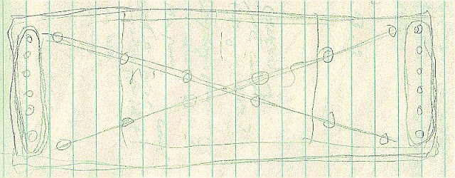
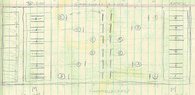
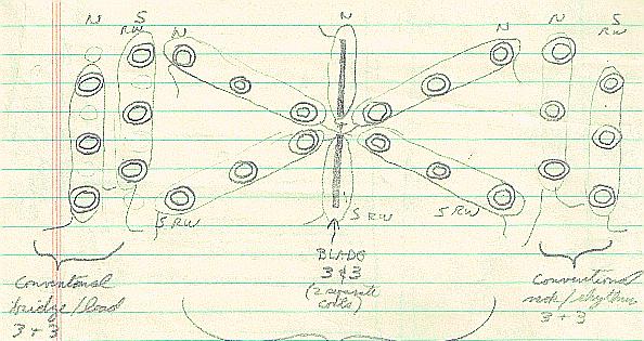
Attached are three sketches. They are more based on pickup positioning ideas than anything else. The ideas are very rough brainstorming, and the sketches are sometimes intended to be transparent views.
The first is a quick drawing showing what amounts to two Strat pickups in the bridge and neck positions, and the crossed config of individual string pickups. This was just an initial idea. The crossed pickups would amount to a Strat-type magnet with a sewing machine bobbin used as a coil form. They could be held in place with a grommet. I know, this is pretty crude but it was just an initial idea.

The second sketch is a tad more involved and takes a bit more explaining. I was considering using a staple-shaped magnet that was held in place by a brass screw and a spring to allow for pole piece adjustment. The coils would have been separate coil forms that would be sandwiched between two pieces of plastic or fiberboard. The design would allow for humbucking configuration. The coils wouldn't have very many turns, and would require some kind of electronic boost. I was considering using the same setup for the crossed pickups, or possibly combining an oddball mix between a single cylindrical pole and a blade piece (obviously with a magnet underneath the top plate) forming the center pickup *and* the pole for the crossed pickup.
Long story short, I figured this would end up being impractical. Wiring harness, electronics, etc. would have been difficult if not impossible to fit in the designated space, and the potential for on-stage failure greatly increased. A guy like Seymour Duncan or Don Lace might be able to refine it and make it practical, but I am not nearly as knowledgeable as those guys. This was a pie-in-the-sky idea.

The third sketch is the compromise I was talking about, and could end up being very workable. The pickups are split amongst three strings each, and there is enough of a spread between poles to allow for a reasonable number of coil turns so active electronics won't be required. The configuration allows for a hum-cancelling config in certain combinations as well. I showed direct magnets in my sketch at the neck and bridge, but there is nothing that says there can't be a kind of interrupted blade pole (shaped sort of like the side shields you see on a Fender Jaguar, only cut deeper). If you really don't want the neck/bridge sections, they could be eliminated and the space used to stretch out the "X". I only went with what I have here because I felt it gave a greater number of combinations.

The third sketch, I feel, is the best compromise for the idea that I have come up with so far. I feel it will give a pretty good usable number of combinations. The part I need to know from you is more about how you envision the switching functions. I feel it is critical to rig the switching to something that makes sense to you - the end-user.
One thing that I have not shown: I would like to see the addition of a piezoelectric pickup into the aluminum box near the neck joint. This would allow adding in more sound of the wood. Frank Zappa did this many decades ago, and he claimed it worked well for him.Again, these are all just rough initial ideas. Any thoughts are welcome. Keep in mind that for a magnetic pickup to work, you need a magnetic field source and a coil of wire with enough turns to generate the output level you require. After that, almost anything is possible.
Note that the actual pickup poles could be shrouded with a plastic cover plate over the aluminum box top, giving the overall appearance much closer to what you have sketched out in your design. As long as the cover material is non-ferrous, it will be invisible to the magnetic field.
Hope you enjoy,
Ben
Thank you Ben, let's pursue the thread under this post - and any comment is welcome.
- Steel Bodied Loic Le Pape Mustang
guitarz.blogspot.com Loïc Le Pape is one of these French guys who makes übercool guitars out of steel - here is his take on the Mustang. Simple and raw, it looks like the ultimate nu-garage rock guitar, isn't it? Also it has interesting...
- Peavey T-60 And T-40 Story And A Happy Christmas. . . . :)
Well, another year almost gone by again! Christmas is almost upon us, the shortest day of the year and tomorrow the days start to get longer. Yippeee! The next set of questions I asked Chip, were as usual, answered in great detail....
- Guild 1963 Jetstar S-100 In Nj For $400
Thi is a rare and unique opportunity to purchase a Guild Jestar S-100 from the Original Owner. this is the 2 pickup model with is much less common than the S-50 single pickup version. It has the Hagstrom-type Vibrato tailpiece and the...
- National Glenwood 99 In Corvallis Or For $500 - Sold!! (alas, I Didn't Get It)
Update: This guitar lwas only onthe market for a few hours - it was listed for sale by a charity Second Hand store in the Corvallis. OFR area - and I spoke to the seller and was 2nd in line but a local buyer showed up with $500 cash in hand and...
- Vintage Hofner 176 Galaxie In Woodbridge Va For $275
Here is a nice looking Galaxie; 3 pickup solidbody guitar made in Germany in mid to late 60's, These Hofner pickups can sound pretty good - sort of a more full range P-90 sound. You don't see these too often. ...
